
It struck me that I get a lot of enquiries about vintage carbs, owing to the Amac post I did some time ago, so I decided to put in a bit about Binks.
See, I had a message from a chap called Peter asking if I could identify the AMAC carburetter fitted to his Monet Goyon two-stroke as he couldn’t find anything like it on the internet. As with most vintage components, there doesn’t seem to be much reliable info around, certainly not on the web, but also in books. It’s a common problem; back in the day, if you had an issue with a component on your motor cycle you telegrammed the manufacturer ‘who would be pleased to assist you’. By the time he went out of business (probably due to spending too much time answering sodding telegrams for nothing) the bike would be worn out anyway so nobody cared too much about saving the information. So today anyone who dabbles in the dark world of ancient motor cycles and needs this information is likely to find it very scarce.
By analysing any carburetter that comes my way and recording differences and settings, I am trying to get enough information to unravel the mystery. I don’t have much in the Binks line but thought it was worth answering Peter’s question here, because while my knowledge is very limited there may be others, apart from Peter, who would find it useful. Also the stupid computer bounced my reply to Peter for some reason, so I hope he will find it!
Here’s Peter’s picture of the carb he is trying to identify…
 At least it’s easy to see why he is struggling to find it on the web; it isn’t an AMAC at all; it’s a two jet Binks that has been fitted with an AMAC float chamber lid.
It’s not altogether unusual for it not to have its original lid because while Binks fitted a clever spring clip to prevent the float chamber lid from vibrating off, unfortunately the ears that hold the clip sometimes break but most of all, the cap itself is a zinc-alloy die casting, the material of choice for detailed castings like the Binks cap with its ‘C.BINKS (1920) LTD ECCLES’ lettering. Unfortunately, while popular with carb manufacturers ever after for its ability to follow intricate casting moulds, zinc alloy (also affectionately known as ‘shit metal’) is fragile and very prone to crumble with age. A nice brass AMAC float cover is a far better thing – and also in short supply – so Peter could probably get a swap.
History tells us that AMAL stands for Amalgamated Carburettors Ltd. The amalgamation happened late in 1927 and consisted of AMAC, Brown and Barlow and Binks. In a letter to shareholders printed in Motor Cycle and Cycle Trader magazine it was explained that amalgamating the three companies – of which Nobel Industries-owned AMAC was clearly the largest – would avoid the current impossible situation of having to predict which manufacturers would want which make of carb, forcing each to hedge their bets on production quantities. Also since each of the manufacturers held patents for certain desirable design features, it had become impossible to make ‘the perfect carb’. An amalgamated company could pool resources and operate effectively without competition..
Charles Binks (1920) Ltd brought a multi jet system to the party. This is Charles, fiddling with one of his early devices…

He had devised a two jet carburettor with a pilot jet system in his early days, having been dissatisfied with the poor slow-running performance of contemporary instruments. This led onto the famous ‘three jet’ and the sports models ‘Mousetrap’ and racing ‘Rat-trap’. Charles himself didn’t live to see the amalgamation, he passed away in 1922.
Peter’s carb is broadly one of these…

…known as the Type A (well, there is another letter indicating size – eg HA for a 1927 3/ 4″ . choke diameter.
This one is a two jet, single lever model. The term ‘single lever’ means it is operated by a single control lever as opposed to a dual lever, like an AMAC where you have to adjust both air and throttle as you ride. A single lever carb can, of course, thus be operated by a twistgrip, which was another of Binks’ inventions that went into the AMAL pot.
Here is a picture of the carburetter dismantled.
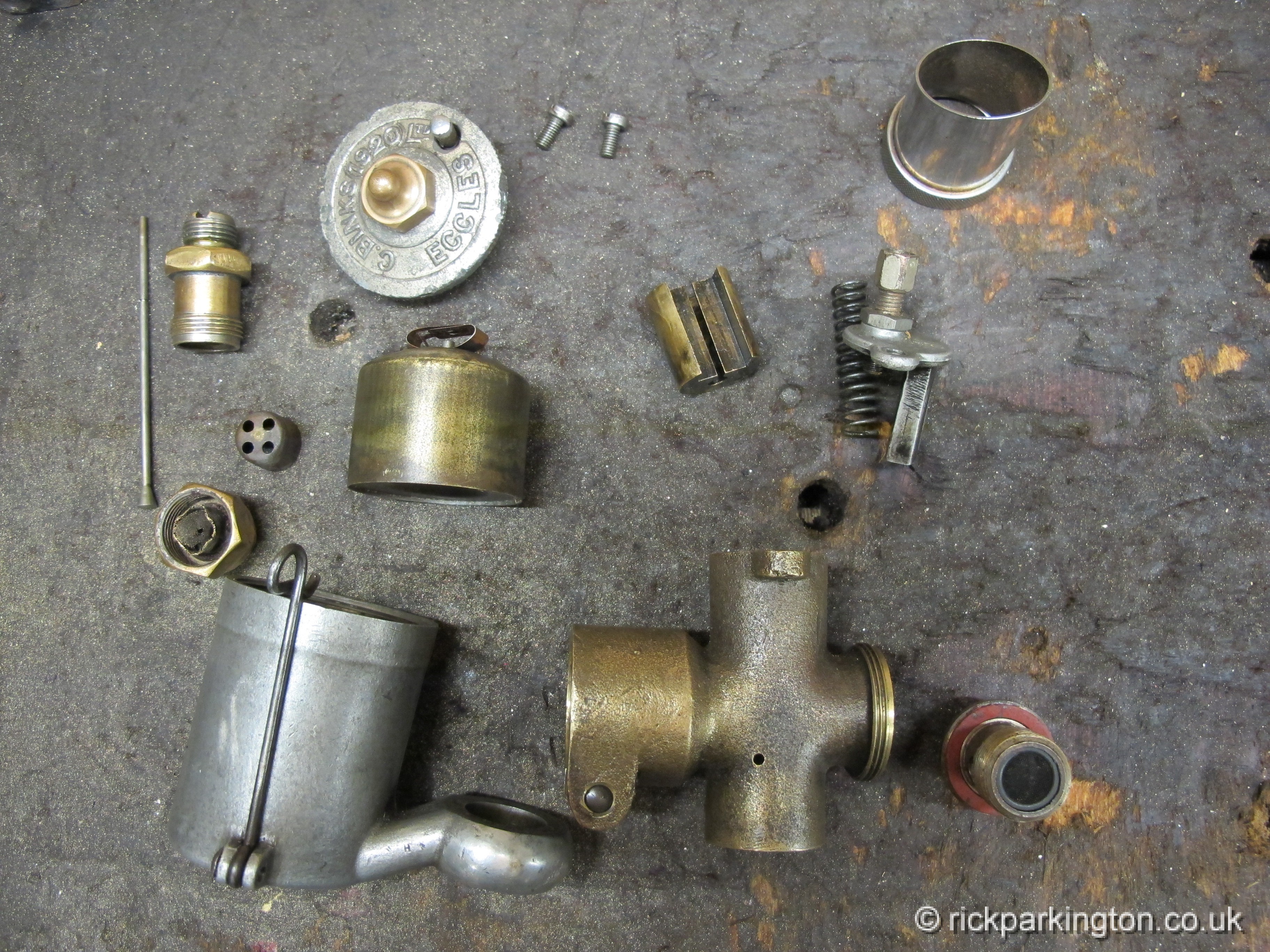
There’s not a lot to it really. Binks’ float was characteristically bell-shaped, the float needle is retained in its jet housing by the cup with four holes in it, which presses into the jet housing.
 The jets are contained in the base of the mixing chamber and so are not visible here. It seems to have been a Binks feature to include a filter in the float bowl bolt. The brass hexagon in the float lid is a repair, presumably the original hexagon crumbled.
Peter wanted to know if he’d got the jets in the right places in his carb. Binks made (to my knowledge) at least three types of jet; there’s one plain type and the others are fitted with a long or short spray tube.
They are fitted with square heads to allow the convenience of being able to remove them with a clock key. Which is perhaps less simple nowadays but was probably the equivalent of a mobile phone ‘app’ in the day. In later years Binks appear to have soldered ‘organ pipes’ into the carb jet block and all the jets are the standard type seen on the left here, so you don’t need to know which length goes where.
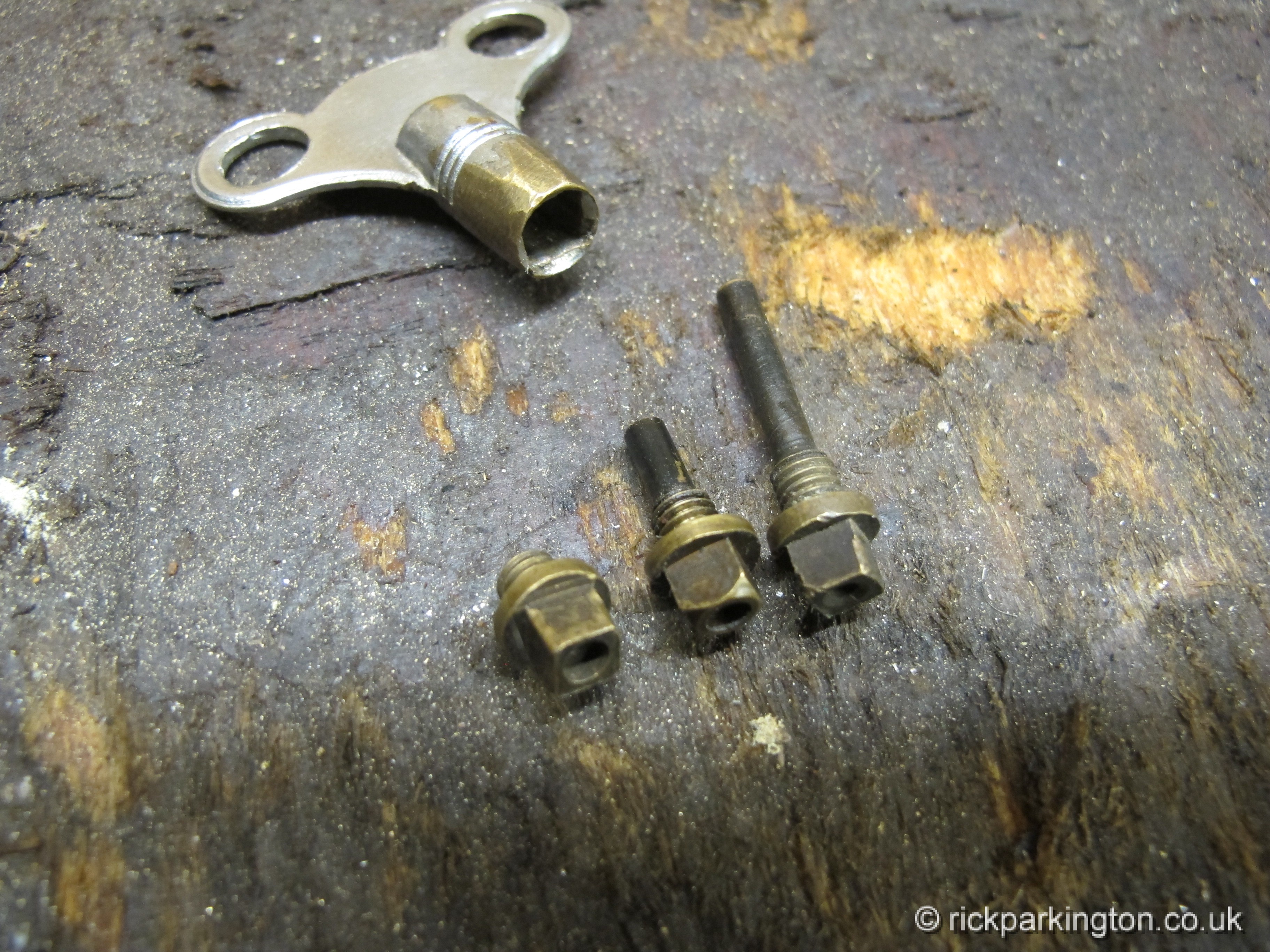 It appears, according to Peter’s pictures, that he has got it right; the jet with the longest spray tube is located nearest to the intake (or bell-mouth) end of the carburetter. Just to be sure I checked another Binks I have…
 Similar sort of thing bit with a longer inlet pipe. This is typically found on side-valves and especially when the magneto is fitted behind the cylinder, on a side-valve obviously, the carb comes out low enough to get in the way of the magneto. Incidentally you can see here why the other carb has a repair on the hexagon…
But this carb has a secret:
 Although it is made by Binks it came off a 250cc Blackburne engine from a Ransomes mower and for some reason Ransomes insisted on using their name on the carb – or maybe arranged with Binks to cast their own design of mixing chamber. But Ransomes weren’t the only ones…
This is the carb from Judy’s 1928 Scott Flying Squirrel. You can see the tombstone-shaped three bolt mounting flange exclusive to Scott and the steeply angled float chamber reflecting the angle of the inlet port on these bikes.

The Scott carb is unusual in being three jet but not to be confused with the much earlier 3-jet Binks

I have a suspicion that he third jet is to do with the carb being for a two stroke. In this case the longest of the three spray tubes is in the middle, the shorter at the intake end. Assuming it’s correct anyway…
And here’s another thing, what have we here; a couple of early brass Amals?
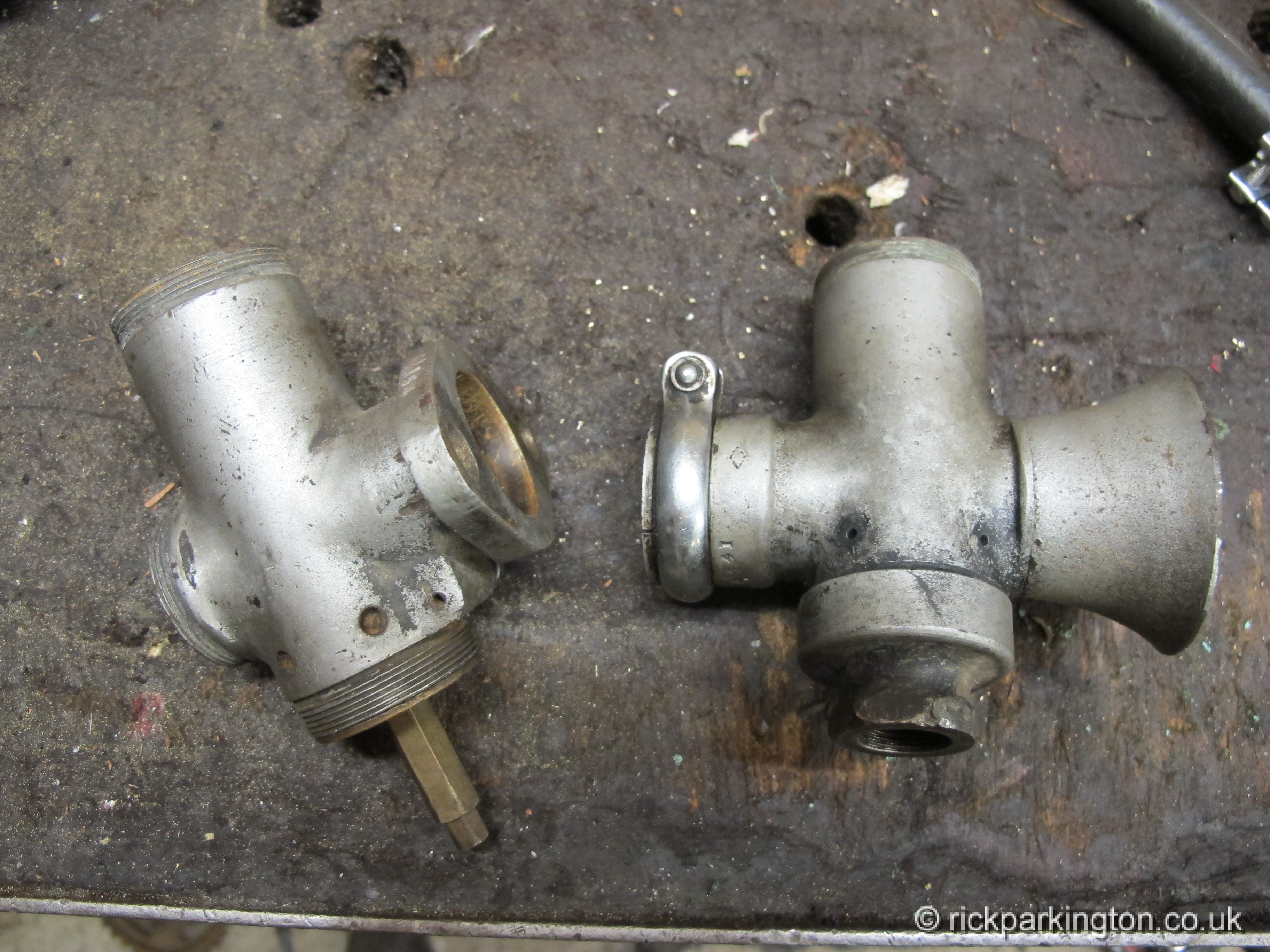 Nope, the one on the left is an Amal but the one on the right is an Amal-Binks, a post amalgamation variant fitted to a few bikes in the last years of the ‘twenties.
 There’s the trademark filter and the two square jets and once again the longer jet is nearest the intake.

To finish, originally Binks (like Amac) used their own size markings rather than the ‘CC per minute at a given head of pressure’ utilised by Amal so don’t expect to find typical Amal sizes on Binks jets unless it is a late carb from the Amal-Binks era. Conversion charts can be found in the Radco Vintage Motorcyclists Workshop book or the reprint Amal book of Amac/Binks/B and B information available from elkpromotions.co.uk for £10 part number 23AM1.
Cheers Rick
It’s good to get more info on the pre Amal carbs and how the different features were brought together. One of the effect of that is that I can still get new AMAL floats that fit the B&B carb on the 27 Ariel.
Hi wonder if you might be able help?i own a 1929 AJS M4 350 side valve,which is fitted with a Binks Eccles 2 jet carburetor,which floods when the petrol is turned on,once the engine is started it stops flooding but the engine runs rich,black plug,i know the float needle valve was made and new spring clip was made for the float,this was done professionally
but i suspect the float is the wrong type as is the needle valve, i have been on line to try and get a new float needle valve,but no luck so far,i wonder if know?if you might point me in the right direction,of a restoration or parts?
Kind Regards Terry Gray
Hi Terry,
Apologies for the delay in reply, no doubt you have solved your problem by now! I can’t offer much help except to say that the usual position for a carburettor float is designed so that the fuel sits slightly below the level of the needle jet. Given that this Binks presumably doesn’t have a needle, that is not a great help but from what i understand about other binks carbs (notably the type fitted to the 1928 Scotts, the level should be just below the top of the lowest of the jets (the pilot).
Logically, if it is flooding when the fuel is turned on, either the float is deranged in some way – too heavy, leaking, catching on something or it’s level is too high. Unfortunately which of these is the problem can be difficult to determine because as the level rises, the carb starts acting as an overflow preventing the valve from cutting off whatever the cause. It may be possible to space the float on the needle to lower it for test purposes. It’s also worth trying it with the chamber lid off (assuming it isn’t a top feed type) then you may be able to see what’s happening.
If flooding stops when the engine is running it’s less likely to be a problem with the valve and more probably that the level is just too high and the engine is drawing in the overflow, causing the rich running.
I would try spacing the float so that looking down the inside of the carb with the slides removed the level is just below the top of the pilot jet and take it from there. I don’t think anyone makes Binks float needles – it’s likely there are several types anyway – but having worked out where the float needs to be it may be possible to modify yours permanently somehow.
Once again apologies for the delay. Cheers Rick
hi Rick,
I have an early binks on a 2 3/4 HP Douglas . the jets are arranged across the intake. in radcos book he shows the jets arranged left to right looking from the intake– 1st pilot– Main– 2nd pilot the main is slightly in front of the other two . the throttle slide is a master piece of engineering the two outer jets have cut off valves built into the throttle slide the left one operates before the right one. the center main jet has a small hole right through the slide inline with the tip of the jet and i not sure of the operation sequence . the engine starts very easely but rapidly but chokes up very rich ,if the air valve is opened the engine gives full power so long as the throttle remains shut and the machine can be ridden using the air valve only for control.
i think the jets i have are massively over size and i have no idea if the slide is the correct one.
any help would be appreciated
Regards
Clive Hallam
Hmmm, that does sound like it might be the case, Clive. Although given that Binks jets aren’t that easily found it seems odd that it would have ended up with some that are so wrong. The Binks idea certainly seemed to be to open and close the jets with the throttle slide and the air valve was allegedly to allow cool air into the engine for hill descents (which sounds a bit improbable but there it is) so I guess by riding it on the air valve you are keeping the jets closed and using the auxiliary air supply as a throttle. Early carb manufacturers didn’t seem to specify settings for individual machines in the way that was done later, probably you were supposed to contact them if you had questions. If you can’t find anyone with a working carb to get jet sizes from the only way to see if the jets actually are too big may be to solder them up and redrill them smaller diameter.
Sorry not to be much help!
Cheers Rick
Thanks for this excellent article. I have been unable up until now to find anything on these carbs.
What is not quite clear to me is which way up the jets sit on the base. Do the square sides ends of the jets face to the top or the bottom of the carb ?
Hi there, thanks for that. Yes, it’s difficult there’s quite at of interest in older bikes but information is thin on the ground, so I try to put up whatever I discover. These jets screw upward into the bottom of the jet block so the square sided portion is lowest. Originally the jets had ‘stove pipes’ on top that poked up into the air stream, but these seem to have been added to the actual jet block on later carbs, presumably to simplify jet production.
cheers Rick